Imagine blueprints as vibrant maps, telling not just where walls stand, but whispering the story of a building's beating heart. This secret language is spoken through Understanding architectural drawing symbols, tiny icons that pack a powerful punch.
Think of a lightbulb symbol illuminating a dark corner, or a faucet dancing playfully above a sink. These are the building blocks of architectural communication, ensuring everyone from architects to construction workers speaks the same language. They streamline complex plans, saving time and minimizing costly errors.
The Basics Of Architectural Symbols
Have you ever stared at a blueprint, mesmerized by the intricate lines and cryptic symbols? Fear not, for unlocking this visual language is easier than you think! Let's delve into the basics of architectural symbols, your key to understanding the blueprint's story.
Lines
- Solid lines -These bold strokes define walls, edges, and structural elements. They're the backbone of the drawing, showcasing the building's skeleton.
- Dashed lines -Used for hidden features like plumbing pipes or electrical wiring, they peek through like ghosts revealing the building's inner workings.
- Dotted lines -These delicate marks represent future extensions, potential modifications, or imaginary boundaries like property lines. They whisper possibilities for the building's future.
Shapes
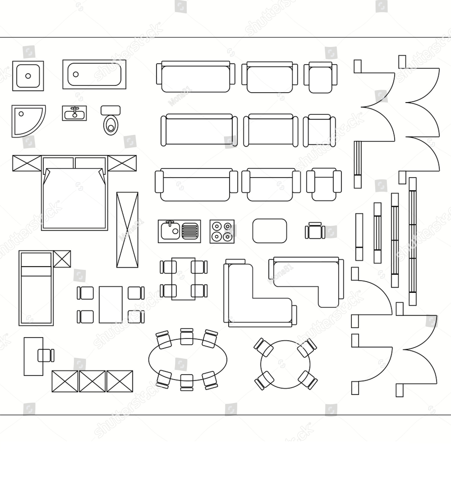
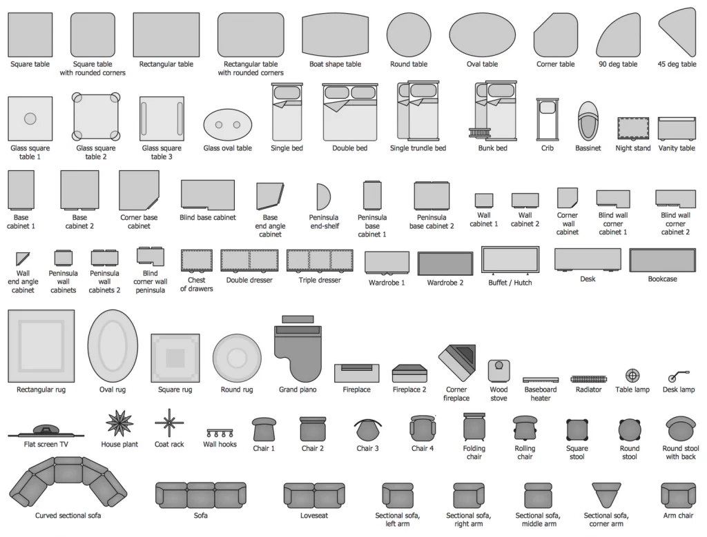
- Rectangles -They're the workhorses of blueprints, representing rooms, doors, windows, and furniture. Their size and proportions tell us everything from the swing of a door to the spaciousness of a living room.
- Circles -These friendly orbs stand for plumbing fixtures like sinks, bathtubs, and even light fixtures. Imagine them as little eyes winking at you from the drawing.
- Triangles -These dynamic shapes often signify stairs, ramps, or roof pitches. They add a touch of dynamism to the blueprint, hinting at the building's movement and flow.
Annotations
- Numbers -These helpful digits label rooms, doors, and windows, allowing for easy reference and coordination between different parts of the blueprint. Think of them as the building's address system.
- Letters and symbols -These cryptic characters represent materials, finishes, and equipment. An "X" might mark a brick wall, while a squiggly line could indicate radiant heating. They're the blueprint's hidden dictionary.
Decoding Floor Plan Symbols
Floor plans are like vibrant maps, guiding us through the spatial symphony of a building. But this choreography relies on a unique language of symbols. Let's waltz through some common ones, decoding the movements of walls, doors, and windows!
Walls
- Solid lines -Our sturdy friends, bold lines define the building's perimeter and interior walls. They're the foundation of the spatial flow.
- Dashed lines -These playful phantoms represent future walls or potential partitions. They hint at the building's adaptability.
Doors
- Single swing -A simple arc denotes a door swinging in one direction. The arc points outwards to show the opening direction.
- Double swing -Two mirrored arcs joined at the base represent double doors, swinging outwards.
- Sliding door -A rectangle nestled within a wall, often with an arrow, marks a sliding door gliding effortlessly to one side.
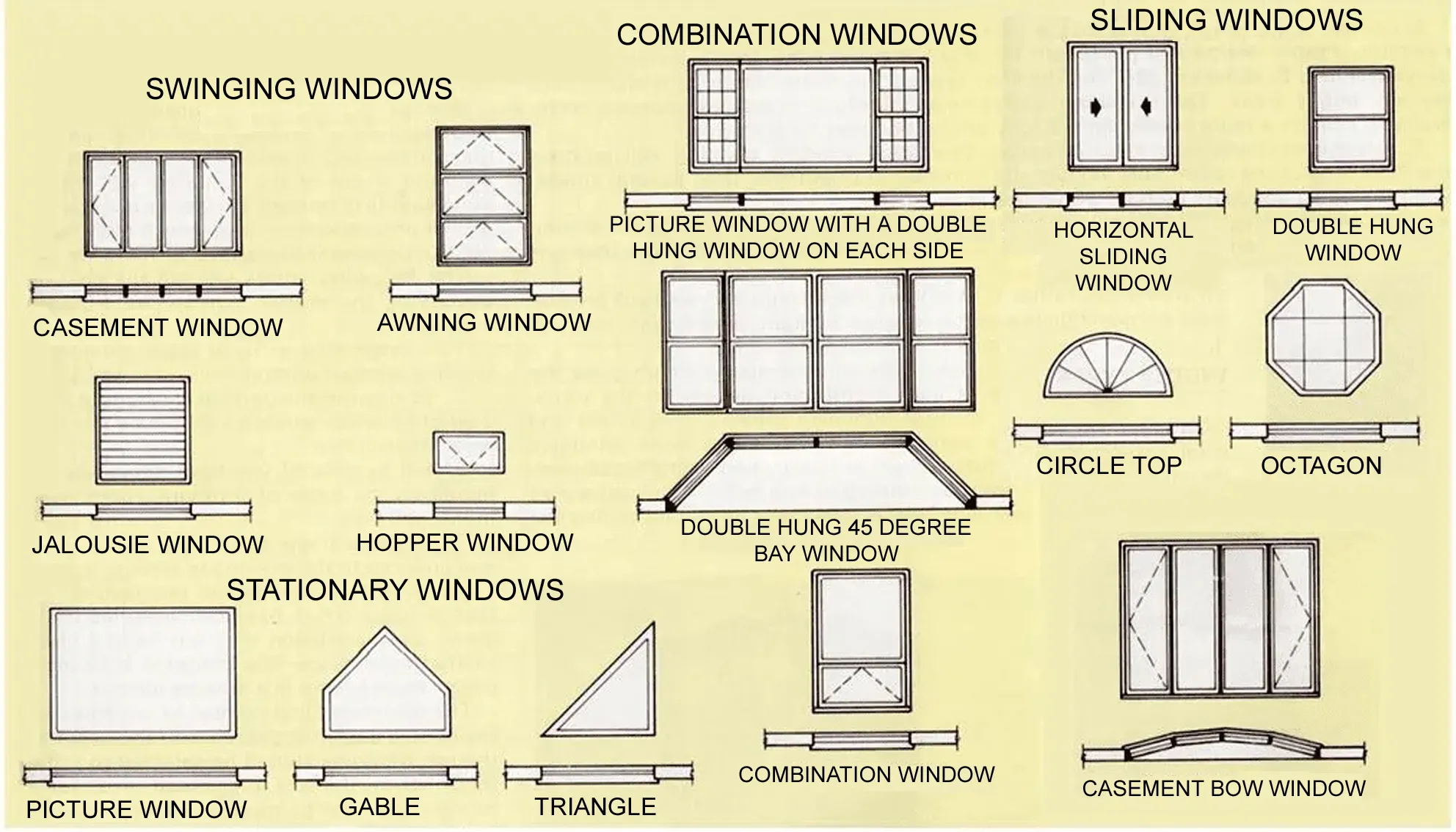
Windows
- Casement window -A rectangle with a smaller rectangle inside signifies a window that swings open on hinges.
- Double-hung window -Two rectangles stacked vertically, sometimes with dashed lines, represent a window where both sashes slide up and down.
- Sliding window -Similar to a sliding door, a rectangle within a wall, often with arrows, depicts a window gliding horizontally.
Electrical And Plumbing Symbols In Architecture
While walls and windows define the spatial language of architecture, the true heartbeat of a building lies in its electrical and plumbing systems. Understanding the symbols used in these plans is like deciphering a secret code, revealing the intricate dance of power and water that keeps our structures alive.
Electrical Symbols
- Outlets -Different shapes represent different outlet types, like the familiar circle for standard outlets or a T-shape for phone jacks. Knowing their locations is crucial for furniture placement and ensuring convenient access to power.
- Light fixtures -From simple circles for ceiling lights to intricate chandeliers, these symbols illuminate the intended lighting scheme, guiding the placement of switches and ensuring balanced illumination.
- Switches -Simple squares or toggles denote the location and type of switches, allowing architects to control the flow of electricity and create functional lighting zones.
Plumbing Symbols
- Fixtures -Sinks, toilets, and bathtubs are represented by stylized icons, their shapes hinting at their function. Proper placement ensures efficient use of space and convenient access to water.
- Pipes -Solid lines, often color-coded, represent hot and cold water lines, waste lines, and vents. Understanding their routes is essential for avoiding clashes with other building elements and ensuring proper drainage.
- Valves -Circles with intersecting lines denote valves, allowing architects to control the flow of water in different sections of the plumbing system. Proper valve placement enables maintenance and potential repairs without disrupting the entire system.
The Significance Of Symbols
These seemingly simple symbols play a crucial role in designing functional spaces. By clearly communicating the location and type of electrical and plumbing elements, architects can:
- Optimize space planning -Knowing where outlets, fixtures, and pipes are located allows for efficient furniture placement and avoids costly clashes with other building elements.
- Ensure safety and code compliance -Proper symbol usage helps architects adhere to building codes and regulations, ensuring the safe and efficient operation of electrical and plumbing systems.
- Facilitate communication -Symbols provide a universal language understood by all stakeholders involved in the construction process, from architects and engineers to contractors and inspectors.
Understanding Symbols In Elevation And Section Drawings
While floor plans reveal the horizontal dance of walls and doors, elevation and section drawings take us on a vertical journey, slicing through the building to expose its inner layers. But navigating this new dimension requires a different set of symbols, a specialized vocabulary to unlock the secrets of these drawings.
Elevations
Materials -Unlike floor plans which focus on spatial relationships, elevations delve into the building's skin. Different textures and patterns represent materials like brick, wood, or concrete, revealing the visual character of the exterior.
Windows and Doors -While floor plans show doors and windows in plan view, elevations depict their full height and profile, including details like sashes, mullions, and transoms. This information is crucial for understanding the visual impact of these elements on the façade.
Openings and Levels -Arches, balconies, and other openings are clearly shown in elevations, along with dashed lines indicating different floor levels and roof pitches. This allows for a comprehensive understanding of the building's vertical composition and interplay of light and shadow.
Sections
Cut Lines -Unlike the continuous lines of elevations, sections utilize thick dashed lines to indicate the "cut" through the building, revealing what lies beneath the surface.
Internal Elements -Walls, floors, ceilings, and structural elements are shown in cross-section, revealing their thicknesses, materials, and relationships to each other. This is crucial for understanding the building's load-bearing structure and construction details.
Hidden Features -Pipes, ducts, and other hidden elements in floor plans become visible in sections, allowing for coordination between different building systems and ensuring efficient service distribution.
Key Differences From Floor Plans
Focus -Floor plans prioritize spatial relationships and circulation, while elevations and sections focus on the vertical dimension and construction details.
Level of Detail -Floor plans typically use simpler symbols, while elevations and sections require more detailed symbols to represent materials, profiles, and hidden elements.
Viewpoint -Floor plans offer a bird's-eye view, while elevations and sections provide frontal or cross-sectional views.
Landscape Architecture Drawing Symbols
Imagine strolling through a lush garden, admiring the carefully curated blend of trees, flowers, and winding paths. But before this vibrant reality takes shape, landscape architects lay the groundwork through a unique language: landscape architecture drawing symbols.
These tiny icons, like the brushstrokes of a painter, bring life to the blueprint, crafting a vision for green spaces that are both aesthetically pleasing and functionally sound.
Plants And Foliage
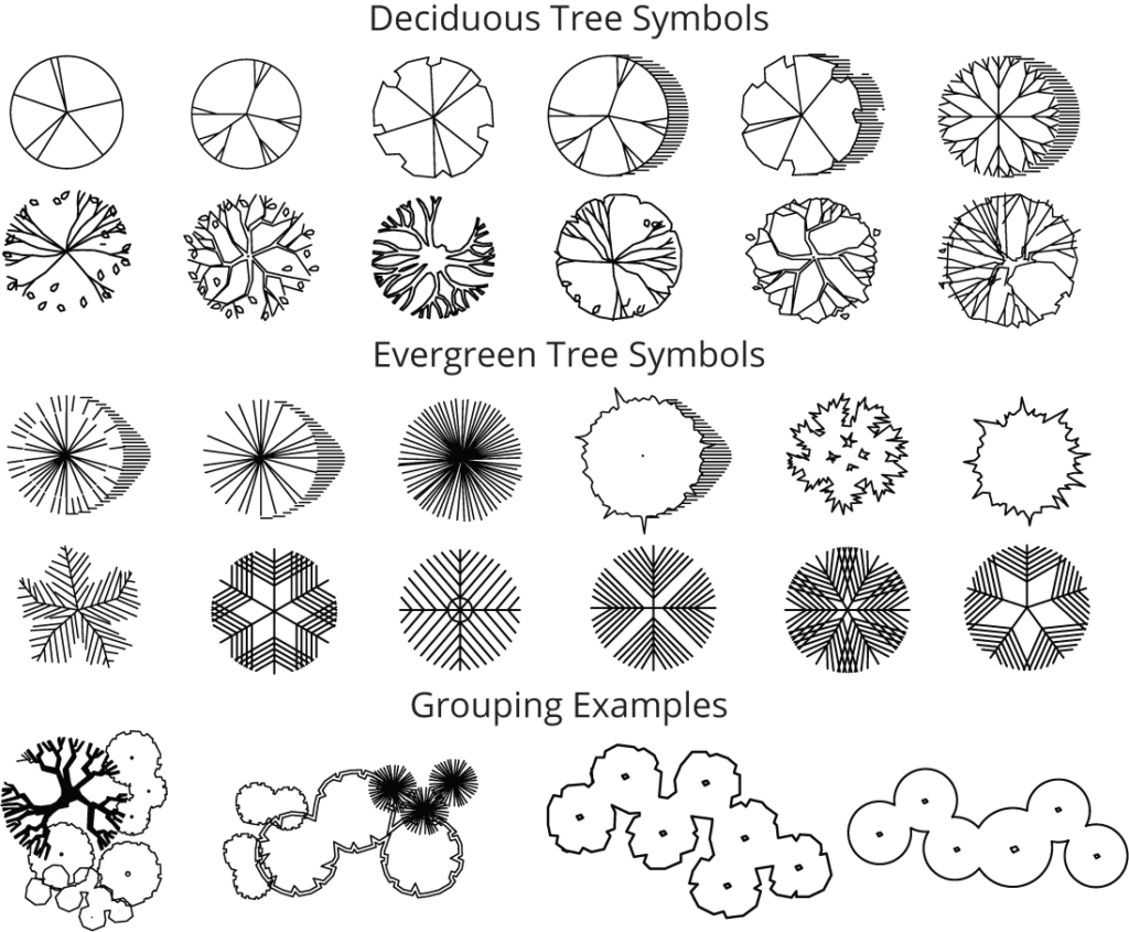
- Trees -Different shapes and textures represent diverse tree species, from the delicate fan of a palm tree to the sturdy silhouette of an oak. These symbols convey height, canopy spread, and overall form, guiding decisions about shading, privacy, and visual impact.
- Shrubs and Flowers -Circles and clusters with varying patterns depict shrubs and flowers, specifying their size, texture, and bloom time. This information is crucial for creating harmonious color palettes and seasonal interest throughout the landscape.
- Groundcover and Vines -Wavy lines or textured patterns represent groundcover and vines, indicating their spread and ability to soften hardscapes or fill in empty spaces. Understanding their growth habits is key to preventing invasive spread and ensuring balance in the design.
Terrain And Hardscapes
- Contours and Elevations -Curved lines with numerical markings showcase the terrain's topography, revealing slopes, hills, and dips in the land. This information is essential for drainage planning, grading, and ensuring accessibility within the landscape.
- Paving and Paths -Different textures and line weights represent various paving materials like stone, brick, or concrete. Understanding the characteristics of each material helps to define pathways, patios, and other hardscape elements that complement the overall design and withstand foot traffic.
- Water Features -Ponds, fountains, and waterfalls are depicted with stylized icons, highlighting their shape, size, and flow. These symbols play a crucial role in adding visual and auditory interest to the landscape, while also influencing environmental factors like humidity and wildlife attraction.
The Impact Of Symbols
Landscape architecture drawing symbols are not just visual shorthand; they are the building blocks of a well-functioning and aesthetically pleasing outdoor space. By communicating plant selection, terrain features, and hardscape elements, these symbols allow landscape architects to:
1. Enhance Functionality -Proper symbol usage ensures adequate drainage, accessibility, and efficient use of space, creating landscapes that are not only beautiful but also practical for everyday use.
2. Maximize Visual Appeal -Symbols convey scale, texture, and color, allowing for the creation of harmonious plant palettes, visually intriguing hardscapes, and a cohesive overall design that complements the surrounding architecture.
3. Facilitate Communication -These symbols provide a universal language understood by landscape architects, contractors, and clients alike, ensuring clear communication and efficient collaboration throughout the design and construction process.
Landscape architecture drawing symbols are more than just lines on paper; they are the seeds of green ideas, blossoming into vibrant spaces that connect us with nature and enrich our lives.
Understanding their language opens a door to appreciating the intricate planning and artistry that goes into crafting captivating landscapes, each one a unique canvas painted with the magic of nature and the skill of design.
Advanced Architectural Symbols And Notations
We've explored the basic symbols that bring architectural plans to life, but the language gets even richer with advanced symbols and notations. These intricate details go beyond walls and windows, revealing the precise measurements, material specifications, and construction nuances that ensure a building's structural integrity and aesthetic vision.
Dimensioning And Scale
- Numbers and Lines -Precise dimensions are the backbone of detailed drawings. Arrowed lines extending from walls, doors, and windows specify lengths, widths, and heights, ensuring accurate construction and eliminating costly errors.
- Scale Indicators -A small ratio like "1:100" tells you the relationship between the drawing and reality. One unit on the paper represents 100 units in the actual building, allowing you to accurately visualize and measure the design.
Material Notations
- Hatching and Crosshatching -Different patterns of lines within walls and sections represent specific materials. Brick walls might have a grid-like pattern, while concrete might have diagonal lines. These notations ensure the right materials are used in the right places.
- Abbreviations and Codes -Short codes like "CMU" for concrete masonry unit or "GWB" for gypsum wallboard provide a shorthand way to specify materials on the drawing. Understanding these codes is key to interpreting the plan accurately.
Advanced Notations
- Levels and Elevations -Numbers within circles denote different floor levels, while notations like "EL. 10'-0"" specify the exact elevation of a point above a datum (often the lowest point of the building). This ensures precise coordination between different floors and prevents structural clashes.
- Structural Symbols -Special symbols like triangles and lines represent beams, columns, and other structural elements. Understanding these symbols is crucial for ensuring the building's stability and load-bearing capacity.
The Importance Of Advanced Symbols
These seemingly complex symbols are not just decorative; they are the lifeblood of detailed architectural drawings. They ensure:
- Precision and Accuracy -Dimensioning and scale eliminate guesswork, guaranteeing accurate construction and preventing costly mistakes.
- Material Clarity -Notations and hatching leave no room for ambiguity, specifying the exact materials needed for each element.
- Structural Integrity -Advanced symbols for levels, elevations, and structural elements ensure proper load distribution and building stability.
- Clear Communication -A universal language of symbols facilitates efficient communication between architects, engineers, contractors, and other stakeholders involved in the construction process.
Software And Digital Tools For Architectural Symbols
The world of architecturalsymbols has gone digital, evolving from hand-drawn lines on paper to precise pixels on computer screens. This shift has brought with it a plethora of software tools and resources that aid in both creating and interpreting these essential elements of architectural communication. Let's explore some of the key players in this digital symphony:
1. Building Information Modeling (BIM) Software
Revit, ArchiCAD, SketchUp Pro -These industry giants are like digital Legos, allowing architects to create 3D models of buildings and embed symbols within them. Walls automatically generate dimension lines, materials can be assigned with specific textures and hatches, and complex symbols like stairs and railings become drag-and-drop components.
Benefits -BIM software fosters a collaborative environment, where symbols are not just visual cues but intelligent data points. Engineers can extract structural information from beam symbols, contractors can access material quantities from hatching patterns, and everyone works with a single, unified model, minimizing errors and streamlining communication.
2. Computer-Aided Drafting (CAD) Software
AutoCAD, AutoCAD Architecture -These classic drafting tools provide a platform for creating precise 2D drawings and incorporating traditional architectural symbols. Libraries of pre-defined symbols are readily available, and users can create custom symbols to suit specific needs.
Benefits -CAD software offers flexibility and control for detail-oriented drafting. Architects can fine-tune symbol sizes, line weights, and hatching patterns to achieve the desired level of precision and clarity. Additionally, CAD drawings can be easily exported to other software or converted to BIM models for further development.
3. Online Symbol Libraries And Resources
Autodesk Symbol Library, ArchSymbol, Architizer -These digital treasure troves offer a vast array of free and paid architectural symbols, from basic door icons to intricate landscaping elements. Users can browse by category, download individual symbols, or import entire libraries into their software.
Benefits -Online libraries provide instant access to a multitude of symbols, saving time and effort for busy architects. They also foster inspiration and discovery, allowing users to explore new symbol variations and experiment with different design styles.
4. Educational Resources And Tutorials
Websites like LearnCAD, ArchiCentral, and BIM Guru -These online platforms offer a wealth of tutorials, guides, and video demonstrations on how to create and interpret architectural symbols in various software programs. They cater to all skill levels, from beginners learning the basics to experienced professionals seeking advanced techniques.
Benefits -Educational resources bridge the gap between theoretical knowledge and practical application. They equip architects with the skills and confidence to use symbols effectively in their design workflow, ensuring clear communication and accurate execution of their vision.
Challenges In Interpreting Architectural Symbols
Architectural symbols, while powerful tools for communication, can sometimes present challenges in interpretation. Misunderstandings can lead to errors, delays, and even costly rework during construction. Let's shed light on some common pitfalls and explore strategies to overcome them:
1. Scale And Dimensioning
Solution -Always double-check the scale indicator on the drawing. Verify dimensions with other elements on the plan to ensure consistency. Use a scale ruler or grid overlay to measure distances accurately.
Challenge -Misinterpreting the scale of a drawing or overlooking dimension lines can lead to inaccurate understanding of sizes and clearances. This can result in doors that don't fit, windows placed too high, or furniture that doesn't fit in designated spaces.
2. Symbol Variations And Ambiguity
Solution -Familiarize yourself with the symbol library being used in the project. If unsure about a symbol, consult the legend or ask the architect for clarification. Look for additional information like annotations or surrounding elements that might provide context.
Challenge -Different software programs and architects may use slightly different symbols for the same element. This can cause confusion, especially for those unfamiliar with a specific symbol library. Additionally, some symbols may lack clarity or have multiple interpretations.
3. Outdated Or Incomplete Drawings
Solution -Request the latest version of the drawings from the architect or project manager. Clearly communicate any inconsistencies or missing information you encounter. If necessary, involve the architect in resolving discrepancies to ensure everyone is on the same page.
Challenge -Working with outdated or incomplete drawings can be frustrating. Missing symbols, unclear revisions, or incorrect information can lead to confusion and hinder proper understanding of the design intent.
4. Lack Of Knowledge Or Training
Solution -Invest in training resources or courses to learn about architectural symbols and drawing conventions. Utilize online tutorials, reference books, and industry guides to improve your understanding. Don't hesitate to ask questions of experienced professionals when needed.
Challenge -Individuals without proper training or experience in interpreting architectural symbols may struggle to decipher complex drawings. This can lead to misinterpretations and hinder effective communication between different stakeholders involved in the construction process.
5. Communication Gaps And Collaboration Issues
Solution -Foster open communication and collaboration throughout the design and construction process. Regularly review drawings together as a team to identify and address any potential issues related to symbol interpretation. Utilize technology like BIM software to create a single, shared model that everyone can access and update.
Challenge -Lack of clear communication or collaboration between architects, engineers, contractors, and other stakeholders can lead to misunderstandings regarding symbol interpretation. This can result in errors being carried through to the construction phase, causing costly rework and delays.
Conclusion
Architectural symbols are more than just squiggles on a page, they are the secret language that breathes life into buildings. From the familiar rectangles of rooms to the intricate lines of plumbing fixtures, these icons hold the key to understanding a structure's anatomy, its intended function, and the architect's vision.
Mastering this language unlocks a world of possibilities. Imagine confidently navigating a blueprint, effortlessly deciphering the dance of walls and windows, and visualizing the flow of electricity and water before a single brick is laid. This knowledge empowers not just architects and engineers, but also clients, contractors, and anyone with a curiosity for the built environment.